


Zoltán Kiss- Area Sales Manager - East Europe - Endrich GmbH.
LED drivers – reliability, and performance factors
12 September 2016

Summary :
Today’s general lighting industry targets more and more LED based solutions. The fixtures’ performance, reliability and also the return of investment are significantly influenced by the quality of the LED driver. According to failure analysis of LED lighting fixtures, the results show fewer than 5% probability of LED chip failures, other 5% may be the fault of other elements and 90% of cases originate from LED driver failures. To take critical performance factors in consideration, – as well as understanding the reliability scores, such as MTBF and lifetime – are necessary to be able to select the right driver from the wide range of available solutions on the market. This paper tries to summarize some of the measures, and point out possible issues of a driver in order to help fixture designers to specify right solutions for the optimum financial and the operational requirements.
1. LED drivers
LEDs require a power supply that can convert AC power to the DC voltage, and regulate the current flowing through the LED during operation, and protects the LEDs from line-voltage fluctuations, such as the ballast used to be to a fluorescent light. LED drivers may be constant voltage types or constant current types. With the use of these electronic drivers variety of extra functions can be integrated into the fixture, integration of all electronic components is a trend against using of discrete components to simplify application. Drivers with dimming capability can change light output over the full range from 100% down to 5-10%. Dimmable drivers can dim LEDs by reducing the forward current (constant current reduction CCR), by pulse width modulation (PWM) via digital control, or by more sophisticated methods like DALI. Most dimming drivers operate using the PWM method. With this method, the frequency can grow up to few hundred Hz to kHz range, so that the LED light appears to be continuous without flicker. The sensitive electronics of the driver is exposed directly to the environmental effects, that fixture should withstand at any time. Therefore it is important to know all the factors that may influence reliability.
Critical requirements for LED drivers are partially performance related, partially reliability related:
Performance related expectations:
- High efficiency – Critical to energy saving
- Dimming feature – Greatly enhances the energy saving feature of the
- Other electrical features (PFC,THD, Ripple)
Reliability related expectations:
- High Reliability – Critical to minimizing maintenance cost
- Long lifetime – Compatible with the expected life of the LEDs
2. Performancemeasure
LED driver plays a crucial rule in controlling the performance of the whole lighting fixture. The diversity of the available drivers makes it difficult to choose right solution, especially due to the fact manufacturers provide different depth of quality of technical information. Drivers which seem to be perfectly fitting for the first sight may perform completely differently in particular conditions, so without knowing exact behavior in all circumstances it is hard to compare products. Being able to place the right questions to manufacturer one should be aware how to specify drives more accurately to achieve the right performance.
Efficiency
The main benefit of using highefficiency LED drivers is the energy savings, main reason that one is about to change to solid state lighting is energy efficiency. Energy savings in highly efficient drivers can be quite significant over the life of the driver. The power dissipated in a 90% efficient driver is nearly half that is dissipated in an 80% efficient driver, so the savings of energy usage over long lifetime of 50.000 hrs can grow large. In addition, less thermal loss of the higher efficiency driver results lower temperature, which can significantly improve product lifetime. The higher heat in the lower efficiency driver significantly increases component temperatures. As known, according to Arrhenius rule, the life of the electrolytic capacitors in the driver decrease by about 50% with each 1 0 degree °C increase in temperature.
Therefore, higher efficiency drivers can easily have a 2-4 times longer projected life. Reliability is also a function of temperature and lowering temperature increases the reliability of all components in the driver. When dimming is applied to reduce the power consumption in inactive times, usually efficiency drops as well. This drop is different for models of different manufacturers designed for the same nominal power. It is very important to check whether the chosen driver solution exhibits the required efficiency percentage at the defined percentages of load.
![Figure: Efficiency vs load [W] for different 40W
drivers, when dimming](assets/img/abra_2_en.png)
Dimming
As we have discussed, dimming is necessary in most of the cases to reduce lighting costs by saving energy in certain times, when full brightness is not needed. It may cause problems of efficiency, if selection of driver is not adequate. Both PWM and linear dimming methods can have also problems with flickering especially at very low diming levels. This should be checked when selecting driver.
Ripple current
The AC/DC conversion of the LED power supply always has some disturbances on the output, this is called ripple, an alternating component added on the DC output voltage. It will force AC current through the LEDs that can cause visual discomfort by flickering the LEDs. During dimming to very low level this effect may get stronger. A ripple frequency of 1 00 Hz or less will be visible, therefore the target is to reduce ripple and flickering as much as possible. If ripple current exceeds the absolute maximum allowable forward current, it may cause lifetime issues with the LED chips as well.
Stand by power consumption and startup time
According to present EU directives, lighting fixtures should consume less than 1W when in standby. New stage of this regulation requires less than 0.5W of consumption only in standby mode and startup time no more than 0.5 sec in certain types of lighting.
PFC
Depending on nominal power of drivers, the power factor, the ratio of the real power flowing to the load to the apparent power in the circuit, may have some regulations. In an electric power system, a load with a low power factor draws more current than a load with a high power factor for the same amount of useful power transferred. The higher currents increase the energy lost in the distribution system, and require larger wires and other equipment. Below 2W no requirement by any directives, however above that level it must be regulated as many drivers will cause increased apparent power, and electrical utilities will charge a higher cost:
2W < P <=5W PF >0.4
5W < P <=25W PF >0.5
25W < P PF >0.9
Usually driver’s power factor is different for different load levels, so designers should consider this fact when using a driver under its nominal load, as the PF is definitively lower than at nominal power, but the power factor of the lighting fixture still has to meet the EU directives. Same applies to dimmed drivers.
![Figure: Power factor vs. load [W] for different
drivers](assets/img/abra_3_en.png)
THD
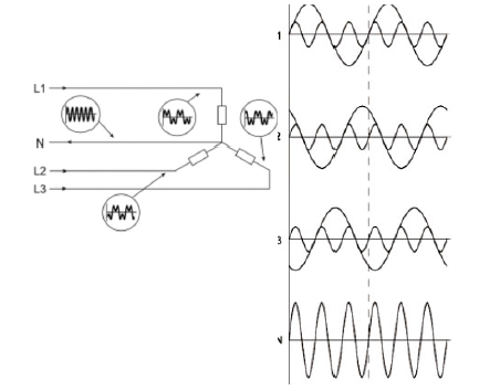
The total harmonic distortion is also a very important property of the LED drivers. A typical switching-mode power supply, like the LED driver first converts the AC mains to a DC voltage by means of a bridge rectifier or a similar circuit. The output voltage is then derived from this DC bus. The problem with this is that the rectifier is a non-linear device, so the input current is highly non-linear. That means that the input current has energy at harmonics of the frequency of the voltage. In asymmetric 3 phase systems, the 3rd harmonics of the voltage could generate remarkable current in the neutral cable. If the switching power supply has high harmonic distortion, the usually thin neutral cable can warm up and danger the surroundings. Therefore to be on the safe side THD is to be kept min under 20%.
3. Reliability : Lifetime versus MTBF
As definition reliability is a probability that the product should perform the expected function under certain operating conditions for a defined period of time. So the reliability is a function of expected operation, conditions and time. Critical requirements for performance of LED drivers are the high efficiency to provide enough energy savings, the reliability to minimize maintenance costs, the long lifetime to be measurable with the LED chips’ lifetime, and the dimming function for further energy and lifetime savings. Usually reliability is quantified with MTBF, but correct understanding of MTBF is a must. In theory the assumption that higher MTBF means higher reliability is true, however there is no direct proportionality between the two numbers.
Mean Time Between Failure (MTBF) represents the statistical approximation of the cumulative hours a number of units should operate before a failure can be expected. It does not represent the expected life of any given unit.
MTBF = (n * t)/ R
n: number of units
t: time in operation
R: number of failures
For instance, if 1 000 units operated in the field for 1 000 hours with 5 failures, the MTBF would be 200,000 hours. This does not suggest that any unit will be expected to operate for nearly 23 years. With other words if this number of product with this MTBF are deployed in the field, on average a failure could be expected about every 5 days if the products are operated 24/7 or about once in every 1 5 days if they are operated 8 hours per day. Reliability can be calculated with the following formula:
R(t) = e (-t/MTBF)
This means, that the probability that a device will survive to its MTBF (t=MTBF) by definition is:
R(MTBF)=e-1=0.3677 = 36,77%
The lifetime of a product indicates how long a product should be expected to survive under normal operating conditions.
If this lifetime is 50.000 hrs, the reliability of different MTBF driver solutions can be calculated:
| Expected service time (h) | MTBF (h) | Reliability (%) |
|---|---|---|
| 50,000 | 100,000 | 60,65% |
| 50,000 | 250,000 | 81,87% |
| 50,000 | 400,000 | 88,25% |
| 50,000 | 500,000 | 90% |
It is well noticeable, that 400% or MTBF increase only results 30% of reliability increase with the same lifespan expectations.
The life of a population of drivers can be divided into three main periods, shown on the reliability „bathtub curve”:
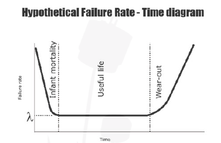
In the beginning of the service period, the production errors may cause infant mortality, the weaker units die off, and the number of failures starts dramatically decreasing. Integrity of design, stress testing and adequate quality assurance provides a tendency to decrease number of early failures. In the period of the useful life failures occur in random sequence, but the failure rate is nearly constant. It is the period of time between starting to use the device and the beginning of the wear-out phase. This is determined by the life expectancy of components used in assembly of the unit.
As components begin to ware out, problems occur at increasing rates, mainly caused by the breakdown of electronic components subject to aging, electrical and thermal stress. This is the period where the calculated MTBF does not apply any longer. MTBF is applicable only during the normal operating life of the product. It may happen that a device with 1 0 years of MTBF wears out in 3 years, no one can predict component wear out on reliable way. Generally quality component as ell as power supply manufacturers target to have a useful lifetime extends past the design life.
4. Reliabilitymeasures
Operating temperature
The temperature at which the driver operates highly affects its lifetime, therefore careful temperature management is a key point of the fixture design. Usually the Tcmax maximum case temperature is the limit for giving a guaranteed lifetime to the driver. Even if there is a built-in thermal protection, it is triggered far beyond this limit, therefore expected lifetime of the driver falls dramatically, unless fixture designer installs external temperature protection.
![Figure : Lifetime [hrs] vs. Temperature [°C]](assets/img/abra_7_en.png)
Electrolytic capacitors and other critical components
The weakest component with the shortest life expectancy determines the life of the whole product. For power supplies, electrolytic capacitors typically have the shortest lifetime expectancy, so life of AC/DC LED driver is normally determined by the life of the aluminum capacitors being used. Long life caps needs to be employed to ensure long life of the LED drivers. Since the life of aluminum caps doubles for every 1 0°C decrease in the operating temp (Arrhenius rule), it is critical to minimize the operating temperature of the electrolytic capacitors. In spite of this fact, failure rates of LED drivers are dominated by the semiconductor devices, which include the main MOSFETs, diodes, control ICs, and opto-couplers. Due to the applied design rules, today the aluminum capacitors only contribute a small portion of the driver failure rates, which are largely dependent on the operating temperature. Typically the failure rate of an LED driver is increased by 25-40% for every 1 0°C increase in the case temperature.
![Figure: E-cap lifetime [hrs] vs. Ambient
temperature [°C]](assets/img/abra_8_en.png)
Efficiency
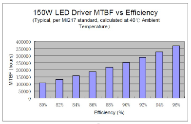
As written before efficiency has a huge impact of lifetime. The less self heating occurs in the driver due to thermal losses, the components are less subjected to thermal stress. The typical life of a 1 50W driver is increased by about 2.5 times as the driver efficiency is increased from 85% to 93%.
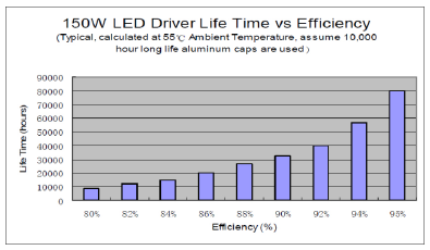
The calculated MTBF of a 1 50W driver is increased by about 90% as the driver efficiency is increased from 85% to 94%.
Solder joints
Solder joint reliability is another issue that can cause trouble due to the temperature cycling, which causes different thermal expansion of the various materials being soldered, therefore risk of cracks in joint. The mechanical stress may also come from using heavy components or from vibration.
Summary of actions to maximize reliability:
- Select quality components, especially the key semiconductor devices
- Reduce operating temperature by improving efficiency
- Provide enough design margins to all components
- Follow strict design procedures
5. Financial considerations
In addition to providing high performance and reliability also financial expectations need to be considered and additional technical features should be involved here. To be able to use more drivers connected to the same circuit breaker provides savings in installation costs. The number of drivers is limited by circuit breakers trigger current. If all drivers have optimized inrush current, more can be connected at the same time without having problem at startup.
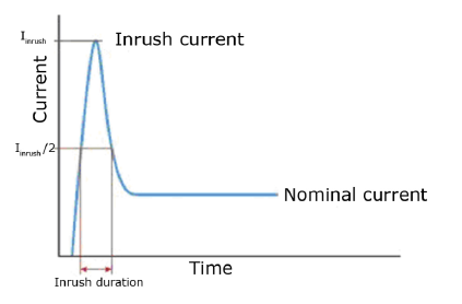
During starting an LED lighting system a huge initial transient current can be maintained, that can be several times higher than the nominal current during normal operation. Typically, these inrush currents last for less than 1 0 ms but still they may trigger the circuit breaker. Inrush current is caused by the charging of capacitors in the power supplies of the LED drivers or because magnetic flux has not yet built up in the transformer in the power supply. Selecting drivers with optimized inrush behavior is cost effective way especially at retrofit solutions simplifying cabling. Endrich’s LUMO series indoor drivers do not use electrolytic capacitors on the input side, creating low inrush current with guaranteed minimal circuit breaker loading, while active surge suppression protects the driver from mains disturbances. Choosing fixed current drivers are cheaper than variable output current versions, however variable ones make it possible to enjoy easy adjustment to provide backward compatibility, when future generations of brighter and more efficient LEDs appear.
Conclusion
To select the best driver by means of lifetime, reliability, performance and financial aspects, several factors should be considered. It is difficult to compare driver specifications between manufacturers, and just base decision on pure purchasing cost is not advisable, as it eliminates too many factors from decision, that may have significant role in the real performance definition. We hope with clarifying above factors the designer has a better chance to make an exact selection. Endrich offers an extensive line of indoor and outdoor LED drivers. As most LED lighting applications are justified on the basis of energy savings and reduced maintenance costs, we focus accordingly on providing high efficiency and long-life products. The portfolio offers products with up to 95% efficiency, power factor up to 0.99, robust lightning protection and IP67 waterproof levels. These products comply with global safety regulations and electromagnetic compatibility standards and feature over-voltages, over-current and over-temperature protection. They are widely used for LED street lamps, tunnel lights and architectural lighting as well as for indoor lighting fixtures.
Endrich indoor LUMO series drivers use special long life electrolytic capacitors specified on 1 0,000 hrs lifetime at 1 05°C on output. The low ripple design creates stable flicker free output and smooth dimming. The self regulated thermal design ensures confidence to provide 5 years ofwarranty.
| Share on Facebook | Share on LinkedIn |
References
This article has been published on the following locations:
| # | Media | Link |
|---|---|---|
| 1 | Elektronet 2016/5 | Elektronet : elektronikai informatikai szakfolyóirat, 2016. (25. évf.) 5. sz. 24-28. old. |
| 2 | Jövő Gyára 2017/3 | 2017. 3.sz. 44-48.o. |
| 3 | Hungarian version | Led tápegységek - megbízhatósági és teljesítmény mutatók |