


Zoltán Kiss- Area Sales Manager - East Europe - Endrich GmbH.
Practical usage of Panasonic GRIDEYE sensor v2.0 – Part 3.
7 September 2017

Summary :
In the first part of our series of articles about Panasonic’s GridEye, we introduced the features of the 2nd generation of this thermopile matrix, and we explained how to use it as a lowresolution thermal camera. In the second part we realized a gesture controlled switching device by using the GridEye development kit as an Arduino shield. We also simulated a movement driven lighting control using this kit connected to a PC. In this closing issue, we are going to realize a standalone Arduino project, which displays the thermal image on an 8x8 high power RGB LED matrix, while a servo motor is used to follow the movement of the target object.
The task: Display the thermal image on a LEDmatrix
The simulation task is about to display the thermal image of a heat source being present in front of the GridEye sensor. In our example it will be the human hand, that acts as an object to detect, and its temperature gradient has to be displayed with multicolor LED matrix. The temperature data will be transferred from the sensor to the microcontroller of the Arduino Due board via the I2C bus as we have seen in the previous article. Then during data processing the thermal image of the hand will be highlighted and displayed in an 8x8 RGB LED matrix, that is driven by the well-known WS281 2B driver IC.

The GridEye evaluation kit also provides the ambient temperature data measured by an NTC, we need this as a reference value in order to be able to highlight the hot-spot given by the presence of the human hand. To make the task simple, we highlight all those pixels out of GridEye’s 64 ones, whose temperature exceeds the ambient temperature with a remarkable portion (min. 5 degree Celsius). The highlighted pixels will be displayed with red, the ambient ones will be displayed with green color. By following the movement of the “red object” with a servo motor we can simulate the driving circuit of an automatic headlamp, that follows the movements of the actor on stage.
Arduino DUE
The Arduino Due is a microcontroller board based on the Atmel SAM3X8E ARM Cortex-M3 CPU. This is the first 32-bit ARM core-based ARDUINO family member. It has 54 digital I/O ports, from which 12 can be used as PWM output. We can control a servo motor with it, which can be used to follow the movement of a heat source in front of the sensor. As mentioned the DUE is a 3.3V card, resulting GPIO ports maximum voltage level to be also 3.3V. Due to this fact we often need to match TTL voltage levels up to 5V by using external circuits such as SN74HC1 25N line drivers (3.3V- 5V) as shown in the previous article.
The RGB LED matrix based on WS2812B driver IC
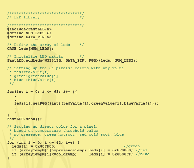
The WS281 2B based RGB LED matrix using 5050 high power LEDs offers an ideal display for GridEye, having exactly the same organization of LEDs than the pixel organization of the sensor. Therefore, it is obvious to assign the temperature value measured by the sensor to a concerning LED’s color.

The LED matrix contains the LED drivers in chains, we can address each standalone LEDs and set up their R, G and B values to mix a desired color. There are no current limiting resistors serially connected to the LEDs, as the WS281 2B drivers provide PWM controlled current source to each LED. The individual diodes can be addressed by sending a serial bit stream to the first element of the chain of WS2812B drivers. The data package contains 3 bytes RGB color values for each LEDs, therefore the total size is 3x8x64 = 1536 bits, which should be sent by the ARDUINO over the serial interface ten times a second to keep pace with the sampling frequency of the sensor.

Each element of the WS281 2B driver chain will forward this data package over their Dout to the Din of the next element of the chain, so each LED will receive and decode its own 24-bit color information.
When all WS281 2B has its own information, the ARDUNINO should send a sync signal to the whole chain in order to enable all LED to display its color at the same time. It is possible to use any colors out of the possible 224=1 6,777,21 6 variations concerning the temperature value of each pixels. Maybe easier solution if only 2 colors are used, one below a certain threshold temperature and one above that to highlight an object present in front of the sensor, we used this method in our example. As ach LED has a nominal current of 3X20 mA, the whole module consumes cca. 3.8A when maximum intensity of all chips is used, therefore there is a need of an external power supply (fig. 4).
")
To drive the LED matrix we can write our own software, but it is even not necessary as ARDUINO society provides several libraries such as Fastled Animation Library (http: //fastled.io/), which gives an simple interface not only for WS281 2B, but also other manufacturers similar platforms as well (Neopixel, WS2801 , WS2811 , LPD8806, TM1 809).
The below code snippet shows how easy it is to control 64 chained LEDs by using one of ARDUINO’s Dout.
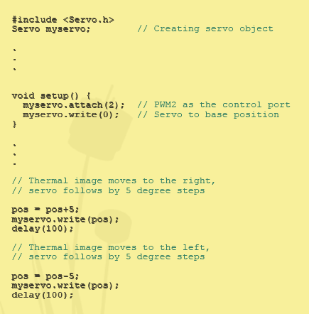
Attaching servo motor

We learned how to attach LED matrix disdday to show the temperature gradient measured by GridEye sensor, but in gesture control applications we also need an intervening device. To model such a control, we attach a servo motor to the Arduino and command it to follow the direction of the movement of the human hand.


Depending on the power consumption of the servo motor either an external power supply or one of the Vdd pins of the microcontroller board will supply the energy. The positioning is done through one of the PWM (pulse width modulated) outputs.
Thanks to the Arduino society and the available libraries we can skip writing complicated software, we only need the free SERVO library.
The below code snippet describes how to set the position of the axe of the servo by 5-degree steps to follow the direction of movement of the „hotspot” in front of the GridEye sensor.
Above code examples are not complete programs, our intention is just offering some idea of how easy to realize the tasks. In case of deeper interest, the author is ready to provide more detailed program codes and explanations based on personal consultation.
| Share on Facebook | Share on LinkedIn |
References
This article has been published on the following locations:
| # | Media | Link |
|---|---|---|
| 1 | Elektronet 2017/5 | Elektronet : elektronikai informatikai szakfolyóirat, 2017. (26. évf.) 5. sz. 18-20. old. |
| 2 | TechStory M2M | Arduino Due alkalmazás GridEye szenzorral |
| 3 | Hungarian version | A Panasonic GRIDEYE szenzor 2. generáció használata – 3. rész |