Zoltán Kiss- Area Sales Manager - East Europe - Endrich GmbH.
Practical usage of Panasonic GRIDEYE sensor v2.0 – Part 2.
18 May 2017

Summary :
In the previous article of this series the main features and news of the Panasonic GridEye thermopile matrix sensor have been introduced. In this paper we intend to show how to build a simple, low resolution thermal camera using the evaluation board in Arduino and in PC environment. We will create a device that can detect the approaching of a human hand and based on its presence a relay will be operated simulating a gesturecontrolled switch. The other sample application will be a PC based control for lighting that can follow the movement of an object.
GRIDEYE sensor as an Arduino shield
As it is known the Panasonic GRID-EYE device is an 8X8 pixel MEMS technology-based thermopile matrix sensor, which is able to detect absolute temperature of 64 standalone section of the space in front of the sensor, based on evaluation of the infrared heat radiation of the objects. Grid-is able to detect absolute temperature as well as temperature gradient providing low resolution (8X8=64 pixel) thermal image. To make prototyping easy, Panasonic also developed an evaluation board for the sensor, which is made as an Arduino Due shield.
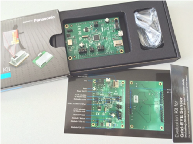
It is important to mention, that the GridEye evaluation board is a 3.3V card, so it can only be used with the Arduino DUE family. To connect to UNO is even not possible as a shield due to the mechanical organization of the board connectors. The Arduino MEGA versions – although they have the same pin layout – are 5V devices, they are not compatible with the GridEye shield due to the different supply voltage levels.
The task
We would like to simulate a simple gesture-controlled switch, that switches on a circuit, when a human hand is present in front of the sensor and switches it off when disappeared. The simulation task requires the read out of the 64 pixels’ data through the I2C interface as shown on fig. 2
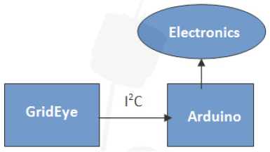
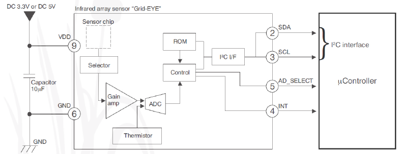
There is also a thermistor available on board, which provides reference temperature of the environment. To keep the solution simple, we use this value as a reference ambient temperature and compare the average temperature value of all the 64 pixels with it. When a human hand is present in front of the sensor, the pixels’ average temperature would exceed at least by 5 °C the ambient temperature measured by the NTC, what we can use to decide whether we should switch the relay on or off.
Arduino DUE
The Arduino Due is a microcontroller board based on the Atmel SAM3X8E ARM Cortex-M3 CPU. This is the first 32-bit ARM core-based ARDUINO family member. It has 54 digital I/O ports, from which 12 can be used as PWM output. We can control a servo motor with it, which can be used to follow the movement of a heat source in front of the sensor. As mentioned the DUE is a 3.3V card, resulting GPIO ports maximum voltage level to be also 3.3V. Due to this fact we often need to match TTL voltage levels up to 5V by using external circuits such as SN74HC1 25N line drivers (3.3V- 5V).
Panasonic GridEye libraries
The Arduino Library required to support the GridEye Evaluation Kit can be downloaded from Panasonic’s support site, and we only need to copy them to the right folder on our PC’s Arduino IDE: <Arduino folder>/libraries. Restarting the Arduino development environment, the GridEye libraries are available and we can reference to GridEye.h, GE_SoftUart.h and GE_SoftUartParse.h header files.
GridEye’s data structure
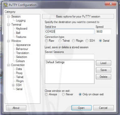
The raw data received 1 0 times a second on the serial port seems to be chaotic for the first sight, however knowing the structure they can be used easily. Any serial terminal program e.g. PuTTY, running on the developer PC and connected via serial interface to the development kit can display these raw data:
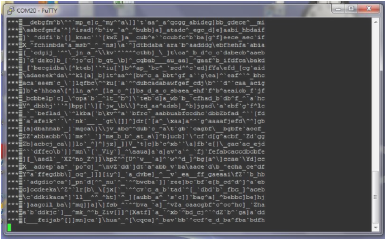
1 35-byte data arrives 1 0 times a second, some of them are control bytes, that need to be filtered out. The remaining data is the NTC temperature data as well as the 64 pixels’ data, which can be fetched out according to below rules:
- 3 bytes header ***
- 2 bytes NTC temperature HL, HH (12- bit signed data)
- 64 X 2 bytes (HL HH) = 1 28 bytes (12 bit two complemens code)
- CR LF (\r \n)
The task has been simplified now, the data structure is very logical, we just have to take care of the sequence of the bytes, as the low and the high bytes arrive in reverse order.
The conversion required for the calculation of the direct temperature values is as follows:
NTC 1 2-bit signed value:
- XXXX S _ _ _ _ _ _ _ _ _ _ _
- If S=1 , temperature is negative, if S=0 temperature is positive
- The binary value stored on the 1 2 bits should be converted into decimal and should be multiplied by the resolution of 0.0625oC in order to get the real temperature: 11 bits = 1024 (211), so over the whole decimal data range (-1023...+1024) it is possible to cover the temperature range of -63 ... + 64 °C.
- Example: HH = 0x01 HL = 2A → Hex-Bin conversion →0000 0001 0010 1010 → positive temperature, and its value is 1*2+1*8+1*32+1*256=298 (decimal) The temperature is = 298*0.0625°C = 18,6 °C
The pixel values are stored in two's complement code, we need a different way to fetch them out:
- XXXX S _ _ _ _ _ _ _ _ _ _ _
- The 1 2th bit refers to the sign as well, however it also holds data: when it is 1 , the temperature is negative, so the decimal value becomes -2048:(-212) instead of +2048.
The program reads out the temperature data 10 times a second from the sensor via the I2C bus and converts the raw data to readable temperatures. To be able to control the operation of the program we display the results in the built-in serial monitor of the ARDUINO IDE attached to the virtual serial port (in our case COM14).

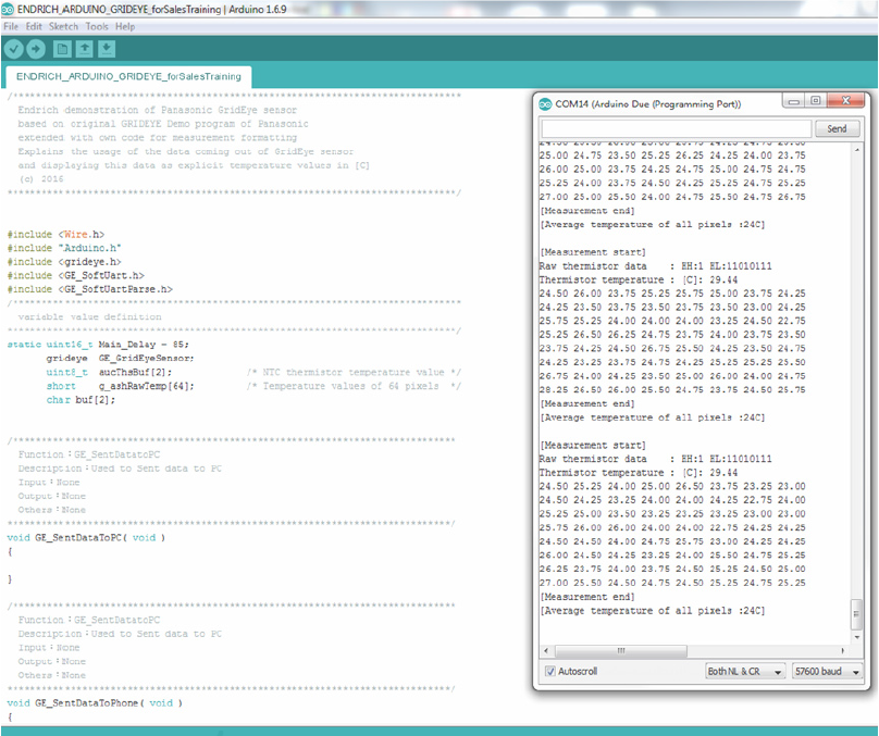
In case the average temperature value of the 64 pixels exceed the preset threshold value (set by variable temperature_treshold = 25°C), we suppose a heat source (the human hand in our case) is present in front of the sensor. (No need motion, presence is enough, this is the biggest advantage of this technology in comparison with doppler radar sensor or PIR sensor technology). Further enhancement could be realized if only those pixels take part in the average creation, whose temperature value exceeds the temperature measured by the NTC on board of GridEye.
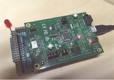
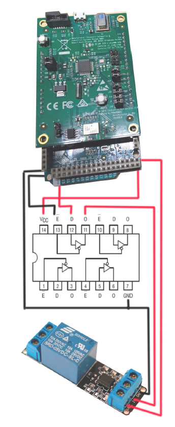
In case of detecting gesture, we use one of the available GPIO port of Arduino Due to set its value to logical “HIGH” (D53 in the sample program). During debugging a simple LED (and a serial current limiter resistor) could be placed between GND and D53 to verify adequate operation. We mentioned before, that Arduino DUE’s GPIOs provide maximum 3.3V signal level when active, which is not enough usually to operate a popular 5V relay module directly. In order to match voltage levels, an external circuit is required, such as SN74HC1 25N logic level converter IC, which contains 4 channels in a 14 pin DIP package.
For driving a standalone relay, we need only one DOUT, as well as only one channel of the logic level converter, and usually the power provided by the digital out port (max 40 mA) is enough to operate it. However, should we use more relays, we need to drive their coils with external power supply. We should never forget about bringing the GND of the power supply to the same potential as the Arduino GND and it is also a good idea to use an overvoltage protection diode. With the described solution we used the GridEye sensor as a presence detector and a gesture controller, that can operate even a line voltage circuit by gestures.
Using GridEye evaluation kit with PC
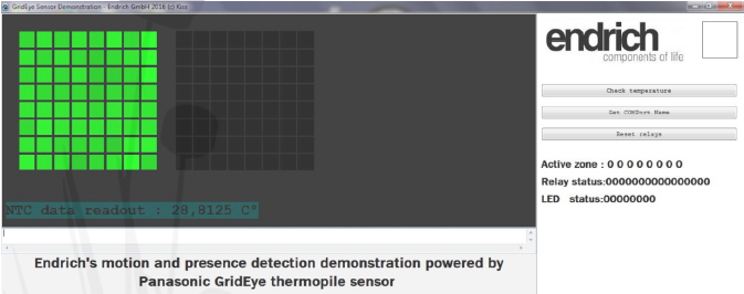
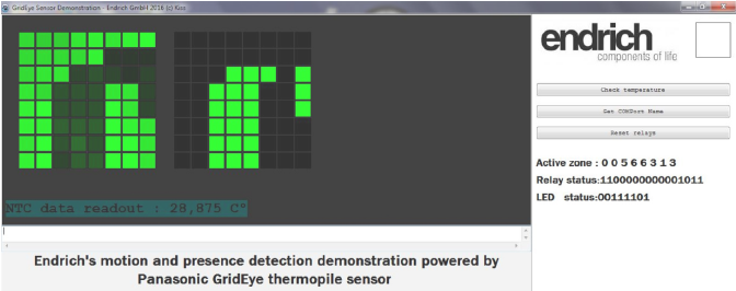
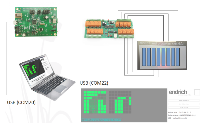
The GridEye Evaluation kit can also be used with a PC connected via USB interface. Using the provided device driver, the USB port can be accessed from the PC as a virtual serial (COM) port. The data structure is the same, user can choose any convenient development system to write the code to convert raw sensor data to visual thermal result. As mentioned there is a free software provide by Panasonic, but we also can make out own version. I have chosen Lazarus as the development system, being a GNU licensed free software, very much like the popular Pascal powered Delphi system or Borland C++ Builder. It is not my intention to detail the software solution, I would rather give a short overview. The application made by this way is a lamp control, that follows the motion of a heat source by lighting up lamps one after the other. The pixels detecting higher temperature than the ambient temperature will be highlighted. Each column is connected to a relay, if the hotspot moves through the column, its lamp will light it up. In this way we can illuminate the moving object, we may “follow” the motion by light. Examples are available on the screen shots. The block diagram of the whole system can be found on Fig. 1 0. The light produced by the 8 vertical high-power LED stripes follow the object moving in front of the sensor, which can be a hand (gesture control) or people walking right and left.
The third (closing) part of our article series will be about a standalone Arduino Due project, that will display the thermal image detected by the GridEye sensor on an 8X8 high power RGB LED matrix, while we will follow the motion of the heat source with a servo motor. This may be a simulation of a project of an automatic stage lamp that follows the movement of the actor on stage.
| Share on Facebook | Share on LinkedIn |
References
This article has been published on the following locations:
| # | Media | Link |
|---|---|---|
| 1 | Elektronet 2017/4 | Elektronet : elektronikai informatikai szakfolyóirat, 2017. (26. évf.) 4. sz. 19-21. old. |
| 2 | Elektronet online | A Panasonic Grid-EYE v2.0 szenzor használata |
| 3 | Hungarian version | A Panasonic GRIDEYE szenzor 2. generáció használata – 2. rész |
| 4 | TechStory M2M | A Panasonic GridEye v2.0 szenzor használata |


