Zoltán Kiss- Area Sales Manager - East Europe - Endrich GmbH.
Transient Overvoltage Suppression
13 February 2012

Summary :
In electrical circuit engineering the main target is to provide the desired functionality of the product being developed. All engineers take a good care of side affects generated by the used elements themselves, such as heat problems are eliminated by good heat dissipation management, high frequency radiation like EMI or RFI , possible harmonic distortions are limited. However there are external affects that can significantly influence the lifetime of the electric circuit, such as overcurrent or overvoltage of the driving lines. Almost all electric boards should contain some elements, which - in normal circumstances - should be „invisible”, but being able to protect the circuit in case of unexpected events like high voltage transients. These transients are mainly caused by sudden load changes of connected circuits, power source fluctuations, electronic disturbances of coupled cables, switching events, lightning or ESD. This abstract is about discussing the possible circuit protections to suppress transient overvoltage with cost optimized solutions.
There are two kinds of transient overvoltage suppression devices by means of action when spikes occur. Their task is to limit the voltage to the level which the circuit behind could tolerate.
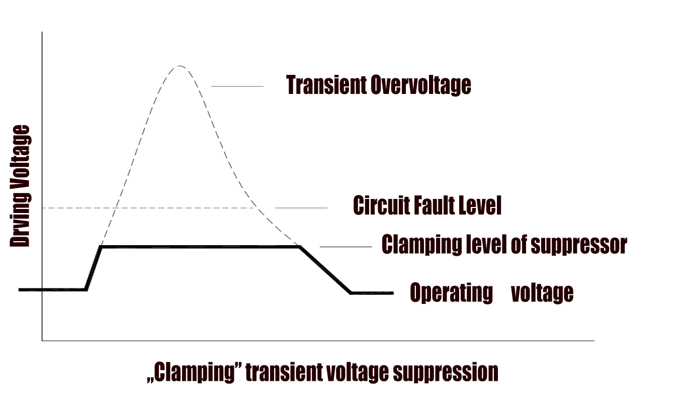
The „clamping” devices begin conducting when the surge voltage reaches the so called breakdown voltage, the threshold these devices are designed for, and maintain a constant clamping voltage. After the voltage returns below this limit, the devices restore to non-conducting state. The high voltage spikes are clipped off and kept on a satisfactory level by clamping. Clamping type suppressors are TVS diodes (Transient Voltage Suppressor Diodes) and varistors ( MOV,MLV, etc).

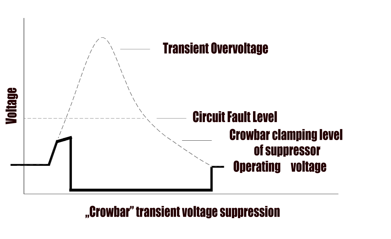
The „crowbar” devices start conducting when surge voltage exceeds the threshold voltage level and force the voltage to drop to a very low level, the protected circuit is mainly connected to ground through a very low impedance. The energy of the transient event must be absorbed by either the source or line impedance and the circuit will not be functional while the TVS device is “ON”. Crowbars could switch to a non-conductive state once the driving voltage returns after the transient passes. Most common crowbars are the GDTs (Gas Discharge Tubes) and Thyristors.

| Device | Advantages | Disadvantages |
|---|---|---|
| Clamping devices |
|
|
| Crowbar devices |
|
|
Suppressor structures
Metal oxide varistors (MOV)
MOVs are voltage-dependent resistors constructed by forming a matrix of zinc oxide grains separated by bismuth or other metal oxide boundaries, which have then similar properties that a semi conductive P-N junction with a breakdown voltage of 2-3 Volts. The array of hundreds of serial and parallel grain boundaries function like hundreds of diodes in parallel and series. More and more junction conduct and the current is distributed through them when surge event occurs. By varying the grain size, thickness and area, the MOV parameters such as current and voltage limits can be defined from chip size to multi kV units. MOVs are symmetrically bi-directional. As cheap devices they are widely used in surge protection, however there is a negative property the so called „ageing”, meaning that MOVs can only conduct high surge currents for a limited number of events. The higher the surge voltage is the lower the number of surges MOV can handle in its lifetime. In case of overstress MOVS first fails short, then after the follow on current causes burning out and open circuit. As the heat is dissipated on the MOV. So much heat can be generated, which may carbonize the PCB, so even in open state leakage current will flow. It is essential to protect the circuit with some fusing device as well. (Good example the 2Pro Devices of TE Circuit Protection detailed in Elektronet 2011/05, where MOV is thermally coupled with a PolySwitch device, which provides overcurrent and overheat protection.)
Multi layer varistors (MLV)
MLVs are designed to suppress surges and/or electrostatic discharge (ESD) and made using multiple, fine grain semi conducting ceramic layers in a specific installation. Every second layers are connected to the same electrodes, this configuration provides significantly larger cross-sectional area for active conduction of transients, thus allowing higher peak energy capability and higher resistances at lower voltages with faster response time than MOVs. The sharp, symmetrical breakdown characteristics of the device provides excellent protection from damaging voltage transients.
Polymer devices
Polymer devices are usually used for ESD protection, due to their special TVS behavior with very low capacitance, they are ideal solutions for high speed data lines. The polycrystalline material provides an electrical characteristics similar to a thyristor’s current-voltage curve. The triggering voltage of a polymer can be in the kV range whilst the clamping voltage is 20-50 V. The characteristics are typically guaranteed for a limited number (few thousands) of surges.
Transient Voltage Suppressor Diodes (TVSD)
Silicon TVS devices contain a P-N junction similar to a Zener diode but with a larger cross section, which is proportional to its surge power ratings. These devices could be stacked in series and parallel in order to extend the power and voltage capability. TVS Diodes can be uni- or bi-directional and they are very fast acting in the sub-nanosecond range of response time as well as low clamping factor (1,33 the ratio between clamping and breakdown voltage). Failure mechanism of a TVSD is the short circuit.
Gas Discharge Tubes (GDT)
GDTs are similar devices to air gaps and carbon gaps except that the parallel electrodes are hermetically sealed and encapsulated in a glass or ceramic cavity filled up with low pressure inert gas. When surge voltage exceeds the limit, the gas ionizes and the GDT „fires”, start conducting the current to ground. These devices are „DC” voltage rated, the size and spacing of the electrodes determine the voltage and current ratings. They can handle very high surge current, but having very slow response time. In OFF state their impedance is very high. Failure mechanism for GDT is mainly open.
Thyristors
Thyristors are multi layered silicon devices, which could be uni- or bi-directional. They are small in size compared to their high surge capability. Response is a sharp, predictable turn-on and it is linear within the specified power limits. The capacitance is very low, as well as the leakage current. There is no lifetime issue, but the switching OFF should be taken in account in design phase. The usual failure mode is a short circuit.
| Device | Advantages | Disadvantages | Properties |
|---|---|---|---|
| MOV |
|
|
|
| MLVs |
|
|
|
| Polymer devices |
|
|
|
| TVSD |
|
|
|
| GDT |
|
|
|
| Thyristors |
|
|
|
SFI Super High Peak Current Suppressor series – cost optimized general solution
SFI has developed new overvoltage protection products, the SMD type SUPER Series , using unique technical and ceramic formulas of multilayer varistor technology resulting so called chip surge protection devices (CSPD). These unique technology researched by SFI has broken the bottleneck of current traditional technologies. Compared to existing products like MLV / MOV / TVS / GDT, the CSPD has outstanding advantages, taking cost optimization, downsizing in mind, a good choice in the area of transient/surge suppressors and overvoltage protective components. In the engineering area, typically the disk type varistors are widely used , if a protection component is required with a high current ability up to 6500A.
With the new high professional multilayer technology suppressor SHC series (Super High Peak Current). SFI provides higher current products at a small size. Compared with other market MLV series products, the new SHC Series upgrades the current ability having much lower aging and also shows a higher temperature characteristic. In most applications the parts can even replace current TVS and Zener diodes.
Features :
- ultra high current handle ability, up to 6500A
- high surge voltage and surge current ability
- ultra high ESD handling ability (ESD Test > 30kV)
- withstands more surge events
- breakdown voltage concentration ratio higher 99.5%
- high nonlinear exponent α up to 50
- ultra low leakage current < 5µA
- high temperature up to 125°C
- RoHS compliant & Lead free SMD types
- compatible with IR reflow and wave reflow SMT process
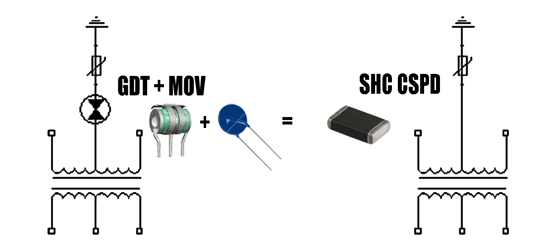
Compared to existing devices with the same current and energy conditions, the size of the CSPD is much smaller, reflow solderable, so extra technological steps necessary for through hole disk varistors could be eliminated. In special cases even expensive GDT and MOV combinations can be replaced with a single SHC CSPD achieving extra space on the PCB and saving cost on the spare parts.

Engineering samples, datasheets and consultation can be requested at the Budapest Office of Endrich Bauelemente Vertriebs GmbH.
| Share on Facebook | Share on LinkedIn |
References
This article has been published on the following locations:
| # | Media | Link |
|---|---|---|
| 1 | Elektronet 2012/1 | Elektronet : elektronikai informatikai szakfolyóirat, 2012. (21. évf) 1. sz. 38-40. old. |
| 2 | Elektronet online | Tranziens túlfeszültség elleni védelem |
| 3 | Hungarian version | Tranziens túlfeszültség elleni védelem |


