


Zoltán Kiss- Area Sales Manager - East Europe - Endrich GmbH.
GigaDevice 32 bit ARMCortex microcontrollers (3.)
16 September 2018

Summary :
In the first part of the series of these articles we reviewed the architecture of the GigaDevice GD32™ARM® Cortex® RISC MCU families, in the second part of the series the evaluation boards for testing the microcontrollers have been introduced. In this paper we show a possible way to start working with them using a popular development system called CrossStudio for ARM 4.1. and show some software examples using the MCU features.
GD32 is a new 32-bit high performance, low power consumption universal microcontroller family powered by the ARM Cortex-M3 RISC core, which targeted at various MCU application areas. GD32 family integrates features to simplify system design and provide customers wide range of comprehensive and superior cost effective MCU portfolios with proven technology and great innovation. The GD32 MCU incorporates the 32-bit ARM Cortex-M3 processor core operating at 1 08 MHz max frequency with Flash accesses zero wait states to obtain maximum efficiency. GD32 series of MCUs also bring much advantage to the end-user. The max speed of GD32 MCU has increased 50% than the market competing products. Code execution efficiency of the same frequency has enhanced 30%-40%. Current consumption of the same frequency has reduced 20%-30%. These performances provide maximum capability and bandwidth options for various market requirements. In order to start testing the GD32 family microcontrollers GigaDevice launched different versions of test boards from basic starter kits to fully equipped evaluation boards, which have been introduced in the previous article.
GD32 Starter kit
The GigaDevice Starter Kits, which we are using for demonstrating some features of the GD32F1 70 series include an I/O Extension Header for all of the package pins to allow quick connection of prototyping. The USB connector of the GD-Link, - a programmer and debugger for the GD32 MCU’s – connects to the PC providing both power supply and data link for accessing the controller and debugging our program.

Development tools CrossWorks for ARM4.1
Comprehensive support for GigaDevice microcontroller devices are available for several well-known standard development tools such as Keil compiler or Rowley’s CrossWorks for ARM providing complete development environment for creating, debugging and verifying embedded applications. Rowley has an evaluation policy, that user can either choose a limited code size version (max 1 6KB), or a fully functional time-limited version (30 day trial) for free. (Keil MDK-ARM Lite Edition offers also free evaluation for a limited code size of 32 Kbytes). CrossWorks for ARM is a complete C/C++ and assembly language development system for – among many others - Cortex-M microcontrollers. The CrossStudio Integrated Development Environment natively built IDE, which takes care of editing, building, downloading, and debugging over SWD/JTAG.
General purpose I/O ports (GPIO)

There are 55 general purpose I/O pins (GPIO) on board at the GD32F1 70C8T6 GigaDevice GD32™ ARM® Cortex®- M3 microcontrollers organized in blocks of PA0 ~ PA1 5, PB0 ~ PB1 5, PC0 ~ PC1 5, PD2, PF0/PF1 , PF4 ~ PF7 to implement logic input/output functions. Each GPIO port has related control and configuration registers to meet the requirements of specific applications. The GPIO ports are pin-shared with other alternative functions (AFs). Each of the GPIO pins can be configured by software as an output (push-pull or opendrain set up by output mode registers), as input, as peripheral alternate function or as analog mode. The maximum speed of the ports are configurable by output speed registers. Each GPIO pin can be configured as pull-up, pull-down or no pull-up/pull-down (floating) by pull up/pull down registers. All GPIOs are high-current capable except for analog mode. Initially all the alternative functions are inactive and the GPIO ports are configured into the input floating mode that input disabled without Pull-Up(PU)/Pull-Down(PD) resistors.
When GPIO pin is configured as Input:

- The Schmitt Trigger Input is activated
- The weak pull-up and pull-down resistors could be chosen
- Every AHB2 clock cycle the data present on the I/O pad is got to the Data Input Register.
- The Output Buffer is disabled.
When GPIO pin is configured as output:

- The Schmitt Trigger Input is activated.
- The weak pull-up and pull-down resistors could be chosen.
- The Output Buffer is enabled:
- Open Drain Mode: A “0” in the Output register activates the N-MOS while a “1 ” in the Output register leaves the port in Hi-Z.
- Push-Pull Mode: A “0” in the Output register activates the N-MOS while a “1 ” in the Output register activates the P-MOS.
- A read access to the Data Output register gets the last written value in Push-Pull mode.
- A read access to the Data Input Register gets the I/O state in open drain mode
When GPIO pin is used as analog configuration:

- The weak pull-up and pull-down resistors are disabled.
- The Output Buffer is disabled.
- The Schmitt Trigger Input is deactivated.
- Read access to the Data Input Register gets the value “0”.
Analog / Digital converters (ADC)
The 1 2 bit resolution analog-to-digital converter uses successive approximation to detect voltage connected to the ADC pins, with a maximum conversion interval of 1`s (speed=1MS/s). For GD32F1 70xx and above the conversion rate is doubled, and the less resolution (1 0 or 6 bit) is selected the higher the sampling speed may be. The ADC converter has 1 9 multiplexed channels, which are used to measure the signals from 1 6 external and 3 internal signal sources (used for the built in temperature sensor, the reference voltage and battery voltage monitoring). Analog watchdog allows the application to detect whether the input voltage exceeds the user's set of high and low threshold values. The A/D conversion of each channel can be performed in single, continuous, scan, or discontinuous mode. The result of the ADC conversion will be stored in a 1 6 bit data register in left or right aligned form. Data may be delivered directly to memory using DMA in order to maximize the sampling speed. The supply voltage of the ADC could be 2.6V - 3.6V, and the measurable voltage range is VSSA_VIN_VDDA. When using the analog watchdog function, an interrupt (IRQ) can be raised when exceeding user’s set up voltage range.
Demonstration of features using the starter kit
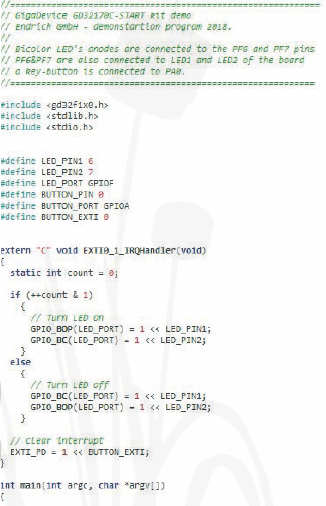
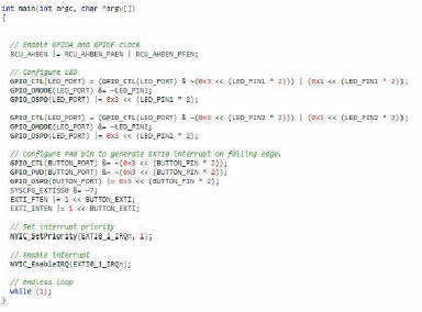
To demonstrate the functionality of the GPIO and ADC of the microcontroller, we made a sample program. The two user LEDs of the starter kit have been used, LED1 and LED2, which are connected also to the PF6 and PF7 GPIO ports of the microcontroller. These two GPIOs are also accessible on the extension header on the left side of the board. To make our demonstration more visible, we connected the anodes of a bicolor LED to the PF6 and PF7 pins of the header, and the common cathode of the LED to the GND pin. This LED will operate synchronous to the LED1 and LED2 green SMD LEDs located on the top of the board. For introducing a user interaction, the key-switch K1 is used, which connects the PA0 GPIO input through a pull-up resistor to 5V, when pressed. This event raises an interrupt, and the handler of this interrupt will light up LED1 and alternatively switches off LED2. At repeated key-press actions, the LED1&2 and the green and red chip of the bicolor LED will alternate.


The following program demonstrates the usage of the GPIO ports as OUTPUT (LED) and INPUT (switch) mode.
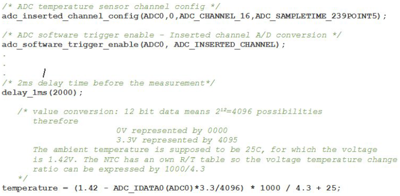
The ADC port demonstration may be done with a small piece of software, using the internal NTC for temperature management. The thermistor is forming a voltage divider with a precision resistor and as the temperature raises, the voltage drop on the NTC will change as its resistance goes down. This voltage is measured by the ADC0 channel. The concerning code snippet is as follows:
The above demonstration was just a small sample to show a very tiny piece of all possibilities the GigaDevice GD32™ ARM® ®-M3/M4 microcontrollers offer to users. Using any of the well-known ARM development tools such as KEIL, IAR or CrossWorks IDEs, and C/C++ language, a huge variety of tasks can be organized. As the GigaDevice 32 Bit MCUs are very similar in functions with the STM32 family of ST/Freescale, many users change to this concept. The hobby people even use today Arduino development system for STM32DUINO projects, and now also GD32 based “DUINO” models are available on the online marketplaces. However for professional users we recommend to use one of the introduced starter or evaluation kits to start with. These provide industrial grade solutions for development and prototyping.

| Share on Facebook | Share on LinkedIn |
References
This article has been published on the following locations:
| # | Media | Link |
|---|---|---|
| 1 | Elektronet 2018/5 | Elektronet : elektronikai informatikai szakfolyóirat, 2018. (27. évf) 5. sz. 21-24. old. |
| 2 | TechStory M2M | GigaDevice mikrokontrollerek - a GPIO és az ADC programozása |
| 3 | Hungarian version | GigaDevice 32 bites ARM® Cortex® mikrokontrollerek - 3 |