Wolfgang Endrich
Alternative circuits for LEDs with 230 V AC driver
2 October 2015

Summary :
Designing a new LED luminaire poses great challenges today – including selecting the right LEDs and a suitable power supply unit. The new AC technology has now substantially simplified this process: It allows direct control of the LEDs with 230 V AC and generates flicker-free light with good dimming properties. Having to develop a dedicated power supply unit can significantly delay a new project. It is much easier to use AC technology with direct control through 230 V AC – with obvious advantages: In addition to considerable cost reductions, LEDs from different manufacturers can be used and combined in one circuit. It is also possible to use a much smaller power supply unit which can be integrated unobtrusively into any housing.
Direct control with 230 V
Directly controlling an LED with 230 V may sound puzzling, especially with regard to the so-called safety extra low voltage. Appropriate safety measures and insulation can quickly dispel these doubts. A special IC from euroLighting allows LED driver circuits to be operated directly with 230 V AC while generating flicker-free light. The 230 V mains AC power is rectified and fed into an AC direct driver without smoothing. The driver pulses with 1 00 - 1 20 Hz and operates the LEDs with constant current and a voltage between 60 - 70 V. This produces the special advantage that LEDs from different manufacturers specified for voltages between 2 - 70 V can be controlled directly. With an operating voltage of 70 V, numerous DC LEDs with different voltages (max. 70 V) can be directly operated in a group. So if an LED has an operating voltage of e.g. 2 V, up to 35 LEDs of this type can be connected in series. The circuit and the required capacity can easily be expanded through the use of further ICs.
Different dimming concepts
In Germany and in Asian countries, numerous products have already been equipped with AC technology for many years. It has proven successful e.g. in retrofit lamps, GU1 0, ceiling spotlights, ceiling floodlights up to 1 20 W, area luminaires with 62 x 62 cm and LED tubes. The market also offers numerous ICs which can be used to implement AC direct circuits. They have one significant difference, though: These circuits can generally be dimmed, but in two ways. (Figure 1 )
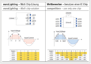
Group 1 , the IC EL01 offered by euroLighting and the circuit created with it, allows simultaneous dimming of the entire luminaire. That means all LEDs are dimmed evenly. (Figures 4c-e)

The EL01 LED modules can easily be dimmed without changing the luminous flux modulation: Fig. 4c: Luminous flux modulation of the EL01 LED module, dimmed to 5 W Fig. 4d: EL01 module dimmed to 2 W Fig. 4e: EL01 module dimmed to 1 W
Group 2 from competitors implements sequential dimming of individual assemblies. This involves supplying individual groups with full power and adding more groups if more brightness is required. This has certain disadvantages: Not all LEDs can be dimmed at the same time so that the thermal load varies and is not distributed evenly across the entire area. The circuit created with this system uses only one central IC. (Figures 4a-b)
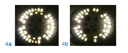
Fig. 4a: LED module dimmed to 6 W: The luminous flux modulation is approx. 9 ms. Six LEDs are already less bright. Fig. 4b: LED module dimmed to 4 W: Some LEDs are already off.
Group 1 uses several ICs which ensures an even thermal load. This makes a useful life of 50,000 hours absolutely realistic. Furthermore this IC features an NTC characteristic which is reduced at full power from 85°C to prevent overheating. Long-term tests with group 1 components have shown many advantages: a greatly simplified circuit without electrolytic capacitors and inductivities or transformers, the useful life of the circuit corresponds to that of LEDs with >50,000 hours, uniform dimmability of the circuit without additional circuitry components as well as flicker-free light at all power levels.
Flickerfree light?
Questions about flicker-free light may arise at this point. To be fair, it should be pointed out that fluorescent tubes operated with conventional or low loss ballast also flicker at 1 00 Hz and the light output is reduced at lower ambient temperatures.
Fluorescent lamps operated with an ECG, including energy saving lamps, work at 44 - 50 kHz so that the lamps normally do not flicker. In reality, however, things are a little different. While a higher switching frequency is used, the input capacitors are to small for cost reasons. This causes the high frequency circuit in the lamp to be supplied with a strongly pulsating voltage. This pulsation creates a brightness modulation in the emitted light which is why these lamps often have a rather high level of flicker at 1 00 Hz.
Back to the AC circuits: 1 00 % flickerfree light only comes from the sun or traditional filament light bulbs. However, there are considerable differences between the chip solutions of group 1 and group 2.
Flicker fusion threshold
When evaluating temporal uniformity as a quality criterion for lighting, fast and slow changes have to be considered separately. Fast changes are the temporal fluctuation of luminous flux of the emitted light due to pulsating fluctuations of the input, e.g. with AC operation. A crucial factor for whether this fluctuation is perceived as irritating is the flicker fusion threshold of the eye which also depends on individual circumstances.
If the frequency of the luminous flux modulation is above this fusion threshold we can no longer perceive it. This limit frequency, where periodically occurring stimuli are just starting to be perceived as a stimulus, is called flicker fusion threshold and ranges between 1 0 and 70 Hz. It is also referred to as pulsation. Below this fusion threshold, however, the luminous flux modulation is perceived as an irritating flicker. Eyes are particularly sensitive to this in peripheral vision. Fast moving objects (e.g. lathes) can additionally create stroboscopic effects with the resulting phantom array effect.
Relatively slow changes in illumination can have a rather positive influence on the human state of mind. The variability of lighting through artificial indoor lighting systems is only slowly gaining significance as a quality aspect. Monotonous constant lighting creates a tiring effect in the long term and has no positive influence on concentration and efficiency.
There is DC light and (DC+AC) light. The following applies for dimming LEDs with the usual pulse width modulation (PWM):
W = (Φmax- Φmin)/Φmean
WLED = with ≤ 1W < ∞
Disadvantage: This creates a considerable luminous flux modulation. (diagram)
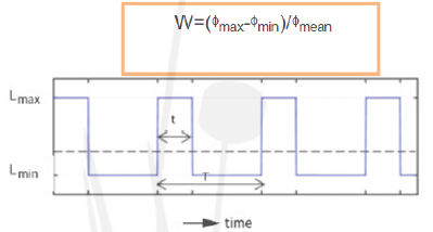
This means that two criteria are important for good lighting: The clock frequency of the LEDs has to be above the flicker fusion threshold of 1 0-70 Hz. The direct AC control for group 1 as described here has a frequency of 1 00 Hz which is clearly above the flicker fusion threshold. Additionally, the light intensity should be as uniform as possible.
That means uniform, rectangular light intensities create a balanced light while wedge-shaped light peaks are perceived as irritating. (Figures 3a+b)
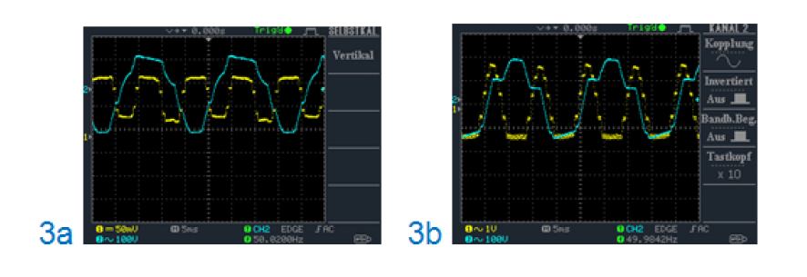
Fig. 3a: EL01 LED module from euroLighting: trapezoidal light curve Fig. 3b: LED module from a different manufacturer: wedge-shaped light peaks (Measuring luminous flux modulation with an ultrafast photodiode. Normal operation and dimmed.) The bottom line: The EL01 modules from group 1 can be dimmed without problems. There is no change in luminous flux modulation.
Other AC LED modules available on the market switch off individual LED groups during dimming and create uneven light due to light intensity peaks.
Implementing circuits
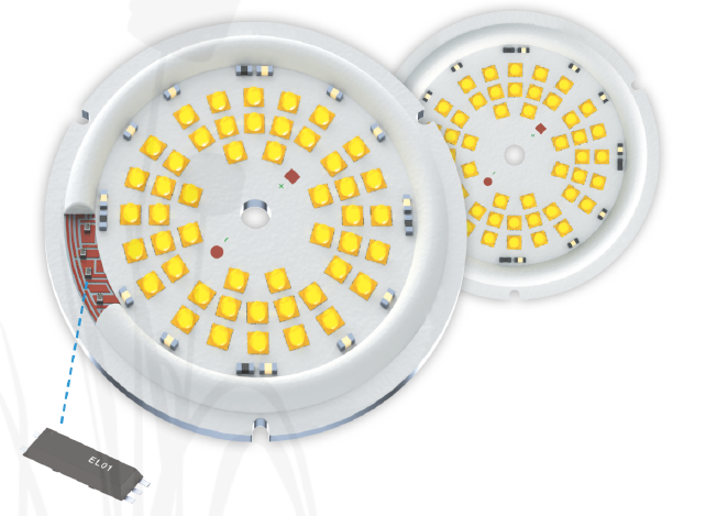
So how can the AC circuits be implemented with chips from group 1 ? Uniform distribution of the resulting heat on the board is absolutely required for preventing hot spots. Good heat dissipation is indispensable especially for higher power levels. That is why the dice for the chips are bonded directly onto the outer edge of the printed circuit board without casing. They ensure uniform heat dissipation because they are distributed across the entire edge of the board, whether square or round. The LEDs are then arranged across the entire free area on the inside of the circuit board.
To protect the dice, but also for insulation, they are covered with an epoxy ring and the LED area is covered with an insulating varnish. The power feeds are double insulated and can be additionally protected against touch with a Makrolon disc. This ensures best possible protection against contact for the entire luminaire unit. The usual heat sink is mounted on the underside or other measures are taken for best possible heat management. The advantages of an AC circuit like this, where LED chips and driver electronics are combined on one circuit board, are very convincing: short development times, space saving design, substantially lower development and product costs, long service life and complete freedom for selecting the LEDs.
| Share on Facebook | Share on LinkedIn |
References
This article has been published on the following locations:
| # | Media | Link |
|---|---|---|
| 1 | Elektronet 2015/6 | Elektronet : elektronikai informatikai szakfolyóirat, 2015. (24. évf.) 6. sz. 16-18. old. |
| 2 | Elektronet online | Hálózati feszültségről működő LED-modulok |
| 3 | Hungarian version | Hálózati feszültségről működő LED modulok - Eurolighting |
| 4 | Revista Española de Electrónica online | LED + driver en una placa – all in one |


