


Zoltán Kiss- Area Sales Manager - East Europe - Endrich GmbH.
Developing human machine interfaces using smart display modules part 2.
15 December 2017

Summary :
The previous article we detailed the properties of DLOGIC’s Smart Display Modules and the possibility of designing a Human Machine Interface. In case of using conventional TFT touch displays the interface design, hardware and software debugging consumes a lot of time, better to take in consideration using a ready, economic, professionally designed smart display module and limit the HMI design to pure software development to minimize human resources and time-to-market of the finished product. After reviewing the advantages of this technology, it is time now to see how easy to implement software HMI by using a cross-platform development tool called Qt on Linux.
Cross platform technology in SDM programming
To make the first prototype of the HMI, we need to buy a development kit, which contains all the components required next to the display module for the development process. We will find in the package a mounting frame, cables, connectors and a PCB offering physical connection to the communication interfaces of the SDM. According to the sales philosophy of the manufacturer, the product purchased for mass production comes without any cables, accessories, even no power supply is provided to keep the price level as low as possible. It is supposed that the required unique mounting is already solved, tailor made connections for the application requirements are already created in the final product. The possibility of supplying the SDM with any DC voltages between 9-36V offers more advantage s and flexibility than to provide a fixed 230V AC to 1 2V DC power supply. When a development kit is purchased the software support is a part of the deal after providing the unique MAC address of the ethernet port of the device to DLOGIC.

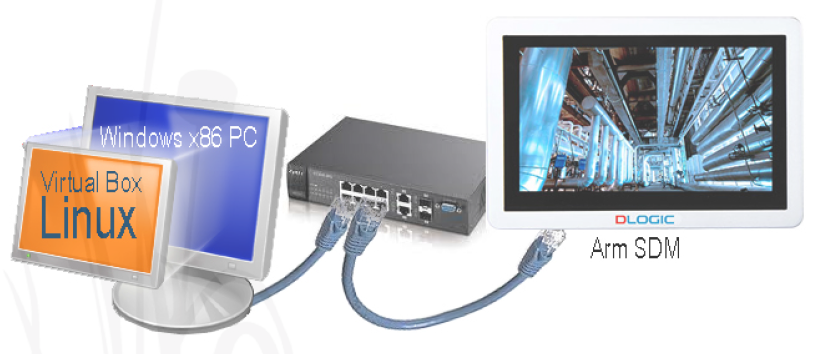
A ready-made virtual computer Debian Linux image, with all software component preinstalled on it will arrive including the Qt Creator cross platform development IDE. The only thing is to install one of the available virtual machine programs such as ORACLE’s VirtualBox on the Windows PC and import the image. A Debian Linux distribution provides good development environment and stability. The essence of the cross-compiling theory is, that the developer uses a computer for writing and debugging the HMI software, and later deploys the executable for a different platform that the compiler itself is running on. The x86 based developer PC and the SDM are physically connected to the same Ethernet network, and the TCP/IP communication between the two systems is possible either by using a terminal emulator of through SFTP protocol.

After installing the virtual machine and importing the tailor-made Debian image the development system is ready to use, there is only one single setting, that the user needs to make: to set up the local IP address of the SDM provided by the DHCP server of the LAN. This IP must be set up and verified on the development PC to be able to send the deployed ARM executable over the ethernet network by using SFTP protocol. The IP address must be written into the HOST NAME field of Qt Creator’s Tools/Option/Devices menu (see figure 3). To obtain and check this IP, we need to start a small preinstalled network configuration program on the display module and set up either dynamic or static IP address for the module on the network. When dynamic IP address is used, we must be sure, that the DHCP server is enabled on the network’s router. Because DHCP may provide different IP addresses to the SDM later on, it is a must to check and adjust this setting also on the development PC. To avoid such an inconvenience, it is highly recommended to use static address, and choose one high number such as 1 92.1 68.1 .21 0 to avoid IP conflicts with DHCP addressed other TCP/IP devices on the network. Advantage of using static IP address is that no need to adjust it more than once in development PC’s QT Creator. When the verification of the connection between the developer PC and the smart display module is successful, we are ready to design the HMI.
Starting Qt Creator project

There are a few types of projects can be started with Qt Creator cross platform development system. Some of them require graphics processor to use above Qt version 5.6 and no more software rendering is available when no GPU is present in the system. Therefore, it may cause problems when using the cheaper line of DLogic SDM module „i” family (Freescale Cortex Arm 9, iMX257), on these DLOGIC SDMs, we can only use widget-based applications. We will use this type of project in our examples. Earlier versions of the board support package had also earlier versions of Qt, so with these on board we may also create simpler Quick and Canvas 3D projects by using the provided software graphics rendering on “i” versions, if the resource requirements are not so high. The software in Qt are written in C or C++, but other language versions are 1 41 also available, even there is an own language called Qt Quick. The project type chosen by us offers a variety of graphics controls (Widget = Windows Gadget), like push buttons, vertical and horizontal sliders, checkboxes, radio buttons to design a state-of-the art HMI. These widgets can be freely placed on the canvas and their properties can be set in the graphic IDE. The required interactions, such as behavior when clicking, double clicking or sliding could be programmed as the event handlers of these controls in C++. We will show examples of these procedures later in this article.

When creating a new project, we need to select from the preinstalled kit selection the target hardware we are developing to. There is a possibility to make a multiply selection, but within one project only those are included, that we defined when starting. It is recommended to always chose the local PC as a target as well as our SDM. When starting the software project, we may design the screen by choosing „MainWindow.ui”, this is the canvas of the SDM, where we can place the widgets to be used for the human machine interface. In our example we used some push buttons, horizontal sliders, and seven segment displays. The push buttons are made to switch devices on and off through controlling some of the general purpose I/O (GPIO) ports, the sliders are used for changing the duty cycle of different pulse width modulation (PWM) controls, that can be used for speed regulation of fans or adjusting backlight brightness of the display. The segment display is to show the status of the last command. In our example we kept the simplicity and the understanding in focus, in real applications of course more complex, professional and trendy screen designs are possible. Before starting to explain the event handler software procedures, this is important to make an overview about accessing the hardware interfaces such as GPIOs, PWM outputs in Linux for better understanding.

Using GPIO ports on DLOGIC SDMs
The Linux distribution of the DLOGIC SDMs makes it possible to control GPIOs through manipulating contents of files in a special file system (/sys/). For all available ports there is a directory containing several files describing different properties of the concerning physical device. (example: /sys/class/gpio/gpio88 for GPIO88 I/O port).
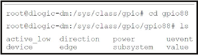
The files listed above contain the properties featuring the device and can be read or written to access or change data on the port. To change the direction to “input” of the port, one can write the value „in” to the direction file by using command echo in > direction, or vice versa echo out > direction will make the port to be output. The value read from or written to the port can be accessed by reading or writing the value file. In case using the echo 1> value command, we assigned logical “high” value to the output, by writing logic „0” level with command echo 0 > value we switch off the port. If we connect a power conversion device such as a FET or Relay module to the output, we can switch high power electronics devices by applying commands to the SDM. (It is important to mention that due to the 3.3V power supply of the ARM controller, the output level of the GPIOs are also limited, so voltage level corrections may be necessary by applying special components between relays and GPIOs.
Using PWMdevices on DLOGIC SDMs

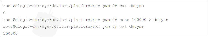
The pulse width modulated (PWM) outputs can be used to decrease the effective voltage of the pin by periodically switching off the power. In figure 6 a FET driver from one of the PWM output ports is responsible to cut off time to time the DC 5V..1 2V power on the connectors of the fan. The average effective value of the voltage will depend on the ratio between the times of having 5V..1 2V and 0V on the fan connectors. Lowering the effective value of the supply voltage makes the fan speed decrease. The figure shows that the GPIO21 PWM output is responsible for controlling the switching frequency of the FET, while the power is switched by the power field effect transistor. Setting up 50% duty cycle (meaning the half of the time the full power is on the fan, and the other half of the time there is 0V) the rotation speed decreases to half. Duty cycle can be set up by writing “on” time in nanoseconds to the concerning file of the related PWM device (mxc_pwm.0):
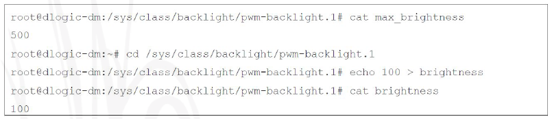
A special PWM device the has been assigned to the backlight module of the DLOGIC SDM, changing the duty cycle of this device will make the backlight dimmed:
The custommade HMI examples
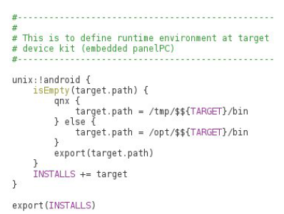
The simple HMI solution introduced in our example is capable to control a few devices through using a few GPIO ports, as well as able to control the speed of a fan and backlight of the TFT via horizontal sliders and PWM controls. After starting the project, we need to set up the runtime environment in the „.pro” file by adding the code provided, otherwise when deploying to SDM without setting up runtime variables, we may be driven to error messages. To control the GPIO ports we should write event handlers for the onclick event of the push buttons.
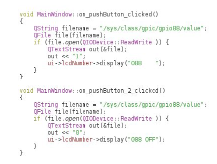
The switching of the port is done through writing special files in the /sys/ file system. Changing to logical level ‘1 ’ GPIO 88 port will switch on, while applying ‘0’ value it will switch off. The event handlers written for the “onclick” event of the concerning two buttons will do the job. The lcdNumber widget is a 7- segment display, we use it to show some status information about the last given command.
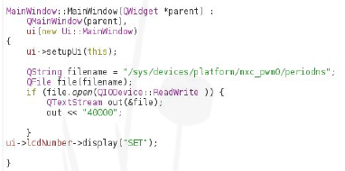
To control the speed of the fan we should use a horizontal slider widget. The set up PWM frequency is 25 kHz, therefore the concerning period time should be 40 000 nsec. This value should be written into the right periodns file when initializing the program. For this we used the event generated when the MainWindow object is created.
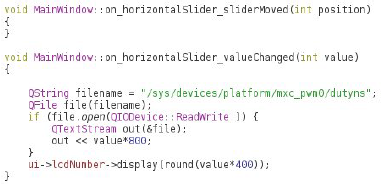
The value of the duty cycle is controlled by the horizontal sliders, which can have a value between 0-1 00. For the value “1 00” 40000 ns (1 00%) “on” time is connected so we need to linearly interpolate for lower values by using value*400 [ns] duty cycle for any cases. This must be programmed in the event of changing horizontal slider’s value.

Using the same methods for all controls required by the HMI we are ready to test the written program. The screenshot on figure 7 shows the possibility to define target environment for testing the code, it is recommended to select here Desktop PC at the beginning, and we can develop and debug our program on the development machine. As this PC does not have the physical peripherals of the SDM, we cannot make a full-featured test, however it is possible to check whether the concerning files are being written right. When debugging shows no more mistakes, we may deploy the finished program to the SDM, by simple choosing the DL-DM-X kit from the selection and Qt Creator will generate now ARM executable, which will be copied to the SDM by Qt using SFTP protocol over the ethernet network.
The simple HMI looks like this:

The advantage of the cross-platform development is that all development and debugging can be made on a desktop PC, and when finished, same tool can be used to generate and deploy executable for the ARM platform. Applying the way of developing HMI by software adaption, a remarkable resource reduction could be accessed as well as time to market of the finish product shortens.
| Share on Facebook | Share on LinkedIn |
References
This article has been published on the following locations:
| # | Media | Link |
|---|---|---|
| 1 | Elektronet 2017/8 | Elektronet : elektronikai informatikai szakfolyóirat, 2017. (26. évf.) 8. sz. 27-30. old. |
| 2 | Jövő Gyára 2017/4 | 2017. (3.évf.) 4.sz. 34-36.old. |
| 3 | Hungarian version | Okoskijelzők használata - ember–gép interfész (HMI) megvalósítása DLOGIC modulokkal 2. rész |